Maximum current subject to the diode used
Terminal thickness: 6.2
| Rigid conductor | Flexible conductor | I | Ui | |
| (mm2) | (A) | (V) | ||
| Ratings | 0.2-4 | 0.2-4 | 321) | 500 |
Products Category
Maximum current subject to the diode used
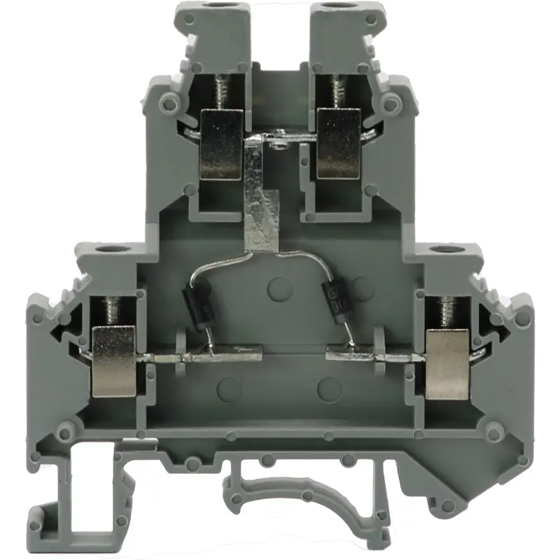
Product Description
Parameters
Certification
Maximum current subject to the diode used
Terminal thickness: 6.2
| Rigid conductor | Flexible conductor | I | Ui | |
| (mm2) | (A) | (V) | ||
| Ratings | 0.2-4 | 0.2-4 | 321) | 500 |
| Description | Type | |||
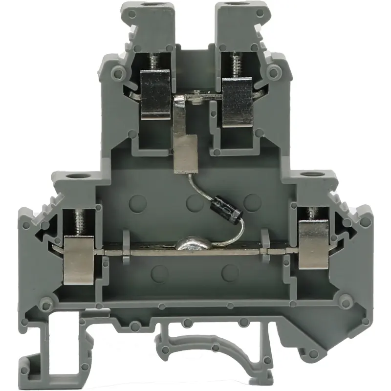
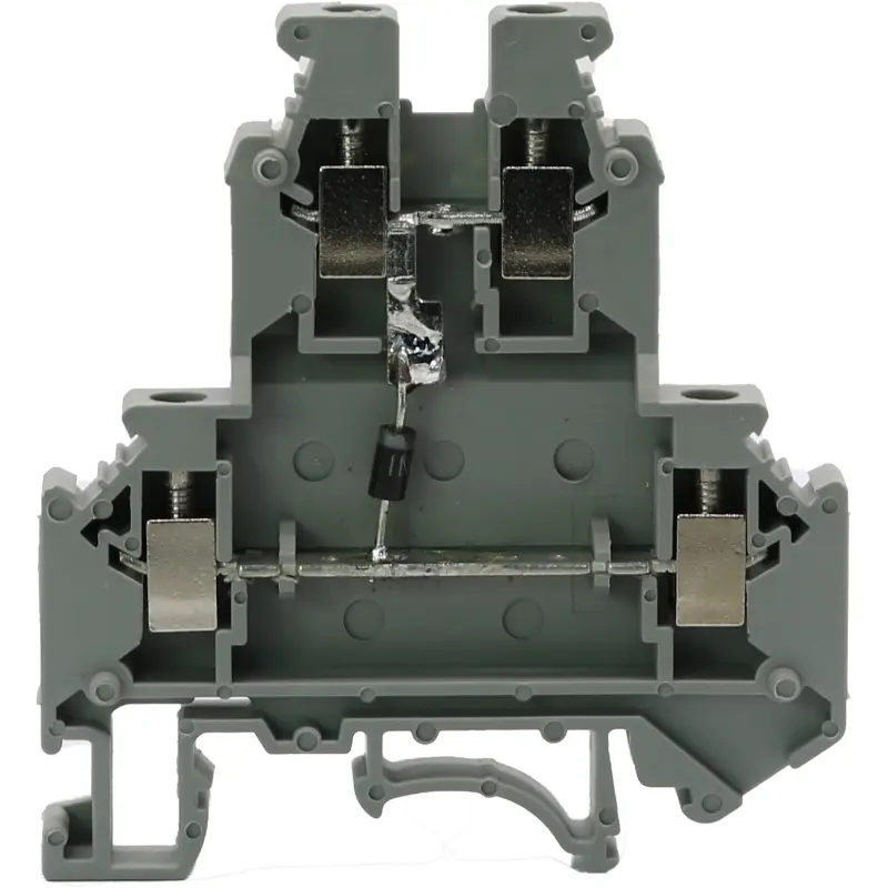
| Unidirectional conducting terminal: | JWD1-4/2 DT/S-X | |||
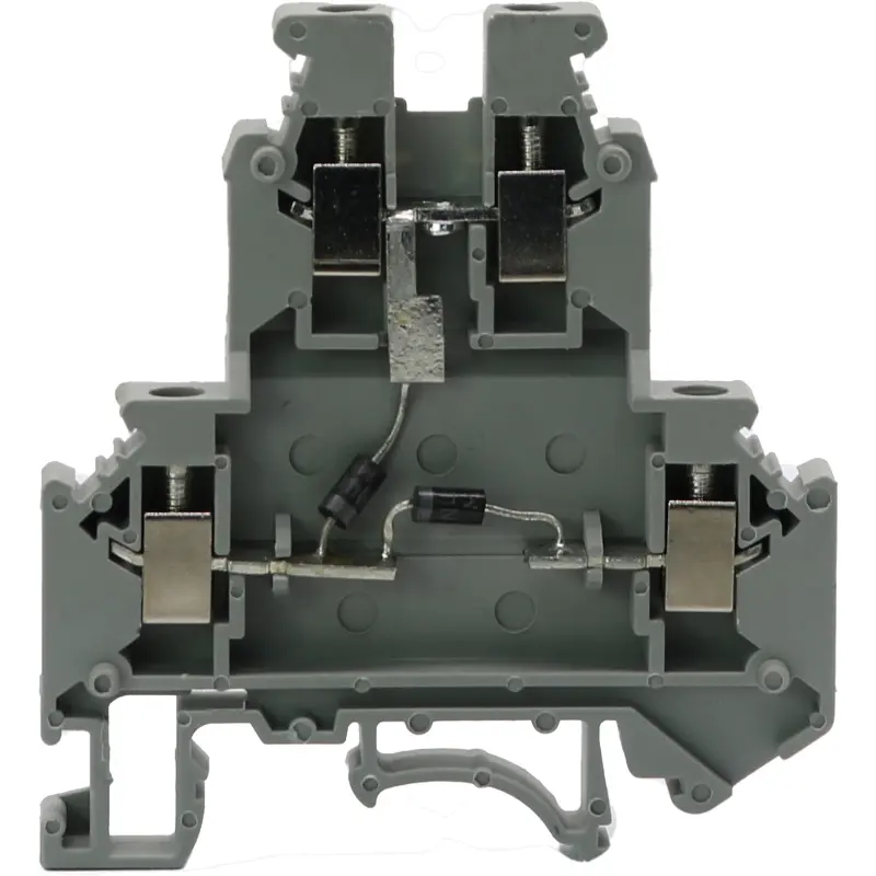
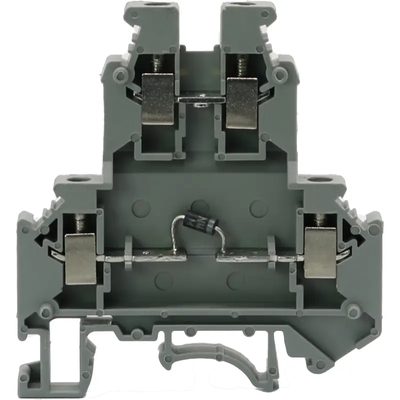
| Connect a rectifier diode between the conducting plates in the upper and lower layers, or between the conducting plates in the lower layer (see the schematic diagram). | ||||
| JWD1-4/2 DT/X-S | ||||
| (1) End plate: (thickness: 2.5) | 2.5-4/2 G | |||
| One additional piece must be attached to the end of each terminal strip set. If it is mounted in the center of the terminal strip, the creepage distance may increase. | ||||
| (2) Compensating end plate: (thickness: 2.5) | 2.5-4/2 BD | |||
| It is used to offset interlayer displacement while it is adjacent to an ordinary terminal. | ||||
| (3) Compensating end plate: (thickness: 2.5) | 2.5-4/2 BD-1 | |||
| It is used for terminal locating and fastening of the terminal strip or for offsetting interlayer displacement while it is arranged with other terminals in the same group. | ||||
| (4) Central liaison part: | ZL6/10 | |||
| It is used to connect terminals with the same specification and form a liaison terminal group; each part has 10 digits (supplied with screws) that can be further divided at will. | ||||
| (5) Connecting sheet: | LJ 6/2 | |||
| For central connection of more than 10 digits | ||||
| (6) Edge liaison part: | 2 digits: | BL 6/2 | ||
| Its role is the same as that of the central liaison part (4); with insulation on the back side; 10 digits that can be further divided at will | ||||
| 3 digits: | BL 6/3 | |||
| 10 digits: | BL 6/10 | |||
| (7) Jumping liaison part: | KL 6/10 | |||
| With the spacer (8), it can connect any non-adjacent terminals in the center. | ||||
| (8) Spacer: | K6 | |||
| Used as a spacer block between the accessory of the jumping liaison part (7) and the conductive part of the terminal | ||||
| (9) Divider: | GP-1 | |||
| It is used to separate two adjacent liaison terminal groups and can be inserted after assembly, without any effect on the overall space. | ||||
| (10) Group partition: (thickness: 2.5) | 2.5-4/2 GF | |||
| Used for separation of each terminal group; with dual effects (visible grouping and electrical isolation) | ||||
| (11) Tag: | ZP6 | |||
| Terminal dimensions | ||
| Thickness / width / end plate thickness | [mm] | 6.2/56/2.5 |
| Height (TH 35:7.5 / TH 35:15 / G 32:15) | [mm] | 62/69.5/67 |
| Technical data based on IEC/DIN VDE standards | ||
| Maximum rated working current / cross-sectional area | [A] / [mm2] | Apr-32 |
| Maximum cross-sectional area of conductors (rigid / flexible) that can be connected if any edge liaison part is used: | [mm2] | 4/2.5 |
| Rated impulse withstand voltage / degree of pollution | [kV]/- |
6/3 |
| Over-voltage category / insulation material group | -/- | III/I |
| Stripping length | [mm] | 8 |
| Screw type | M3 | |
| Torque | [Nm] | 0.6-0.8 |
| Insulation material type | PA | |
| Material flammability according to UL94 | V0 | |
| Rated working voltage / rated working current / wire gauge | UL:[V]/[A]/AWG | - |
| Notes: | ||
| 1. Type JWD1-4/2L DT/... unidirectional conducting terminal is also available. | ||
| 2. If the customer needs the current of 3 A, two diodes can be connected in parallel. | ||
| Applications as follow current protection of relay coil and solenoid valve | ||
| Diode model: IN4007 Diode model: RL207 | ||
| Reverse breakdown voltage: 1000 V Reverse breakdown voltage: 1000 V | ||
| Maximum persistent current: 1 A Maximum persistent current: 2 A | ||


Related products
JWD1-4/2 DT/X-S Screw Type Double Layer Unidirectional Conducting Din-Rail TB
JWD1-4/2 DT/S-XZ/XY-XZ Screw Type Double Layer Unidirectional Conducting Din-Rail TB
JWD1-4/2 DT/XZ-XY Screw Type Double Layer Unidirectional Conducting Din-Rail TB
JWD1-4/2 DT/S-XZ/S-XY Screw Type Double Layer Unidirectional Conducting Din-Rail TB